V Breaker Wiring Diagram Schematic

V Breaker Wiring Diagram Schematic. A wiring diagram is a simplified conventional pictorial representation of an electrical circuit. Wiring diagrams are made up of two things: symbols that represent the components in the circuit, and lines that represent the connections between them.

2 Pole Breaker Wiring
2 Pole Breaker Wiring (Bobby Stephens)
The complete schematic diagram of electronic circuit breaker is given in the image below. A wiring diagram is a simple visual representation of the physical connections and physical layout of an electrical system or circuit. Tach Wiring Diagram - dixco tach wiring diagram, harley tach wiring diagram, pro tach wiring diagram, Every electric arrangement is composed of various distinct pieces.

Typically they are designed for end-users or.

A wiring diagram is sometimes helpful to illustrate how a schematic can be realized in a prototype or production environment.

Bussmann DC Circuit Breaker 100 Amp Surface Mount ...

What You Need to Know Prior to Hiring a Specialist for a ...

BUSSMAN CIRCUIT BREAKER DUAL BATTERY 100A AMP 12V 12 VOLT ...

Hyderabad Institute of Electrical Engineers: motor ...

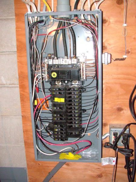
Electric Work: Electrical Panel Projects: Installing A ...

3 Amp Circuit Breaker 440020-3

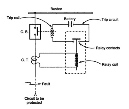
Trip Circuit of a Circuit Breaker | your electrical home

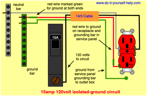
Circuit Breaker Wiring Diagrams - Do-it-yourself-help.com

Inverter 12V DC to 240V DC - Circuit Scheme

Each component ought to be placed and connected with other parts in particular manner. A proper wiring diagram will be labeled and show connections in a way that prevents confusion about how connections are made. WIRING DIAGRAM A wiring diagram shows, as closely as possible, the actual location of all This form of electrical diagram is sometimes referred to as a "schematic" or "line" diagram.

Subscribe to receive free email updates:

0 Response to "V Breaker Wiring Diagram Schematic"

Post a Comment