V Hydraulic Valve Wiring Diagram
V Hydraulic Valve Wiring Diagram. Two stage directional valves are pilot pressure operated. A wiring diagram is a type of schematic which uses abstract pictorial symbols to exhibit each of the interconnections of components inside a system.

In this topic we are talking about how the hydraulic schematic. "Hydraulics is a topic in applied science and engineering dealing with the mechanical properties of liquids.
A wiring diagram is a simplified standard pictorial representation of an electric circuit.

Hydraulic Spool Valve Diagram | Hydraulic Valves Spool Diagram
12v Hydraulic Power Pack Wiring Diagram Sample

How to Wire Hydraulic Power Pack,Power Unit Diagram Design

Aircraft Hydraulic Systems and Hydraulic Power Systems ...

Hydraulic circuit diagram for a system that clamps then ...
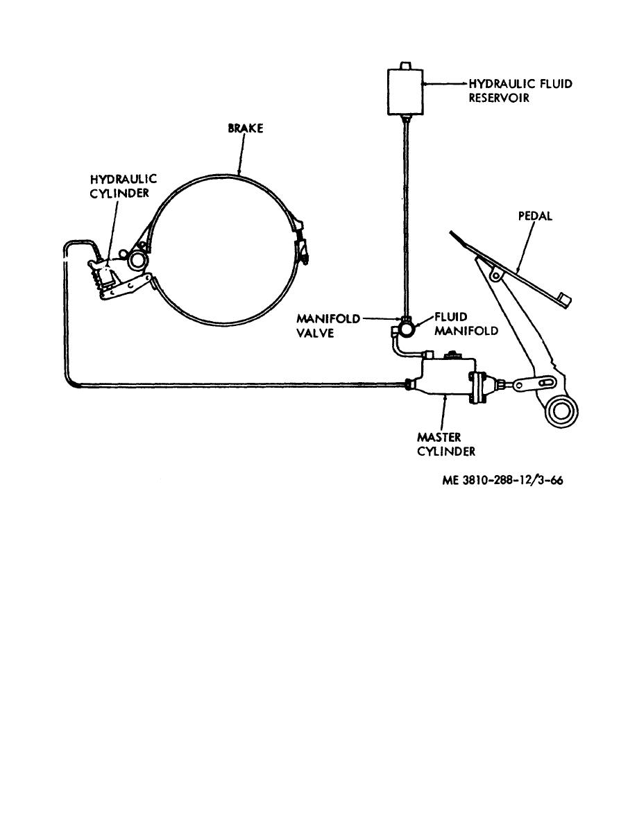
Figure 3-66. Hydraulic system, schematic diagram.

Working on a caterpillar E120 excavator. Operator ...
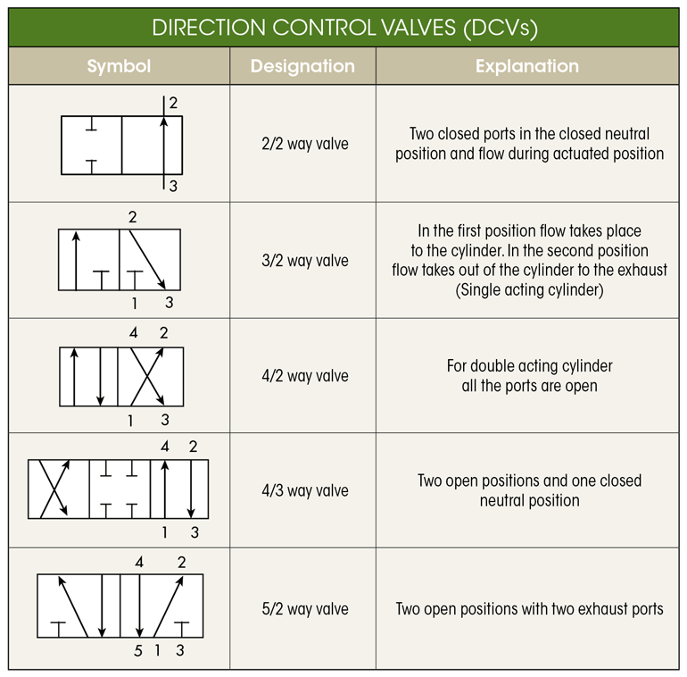
What's the Difference Between Hydraulic Circuit Symbols ...

How to Wire Hydraulic Power Pack,Power Unit Diagram Design
Hydraulic cartridge valves generally refer to directional, pressure and flow control valves that screw into a threaded cavity. For more information about reading hydraulic and pneumatic circuit diagrams, read the next article in this series which describes. Industrial Hydraulics Manual - Free ebook download as PDF File (.pdf), Text File (.txt) or read book online for free.

0 Response to "V Hydraulic Valve Wiring Diagram"
Post a Comment