3 On Franklin Electric Motor Wiring Diagrams
3 On Franklin Electric Motor Wiring Diagrams. If the pump installation does not provide the minimum flow shown in Wired this way, the GFCI will trip only when a ground fault has occurred AND the motor ground wire is no longer functional. Un guide D' installation de franklin electric est.

Franklin Electric is a global leader in the production and marketing of systems and components for the movement of water and automotive fuels.
Three phase induction motors are one of the most popular electric motors commonly found in processing plants or any manufacturing concern.

Electric Motor Reversing Switch Wiring Diagram Gallery ...

Dayton 3/4 Hp 115v Electric Motors Wiring Diagram
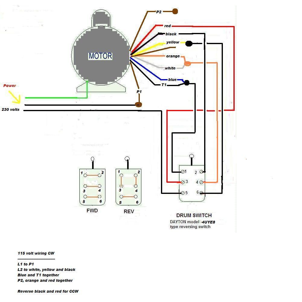
Dayton 3/4 Hp 115v Electric Motors Wiring Diagram
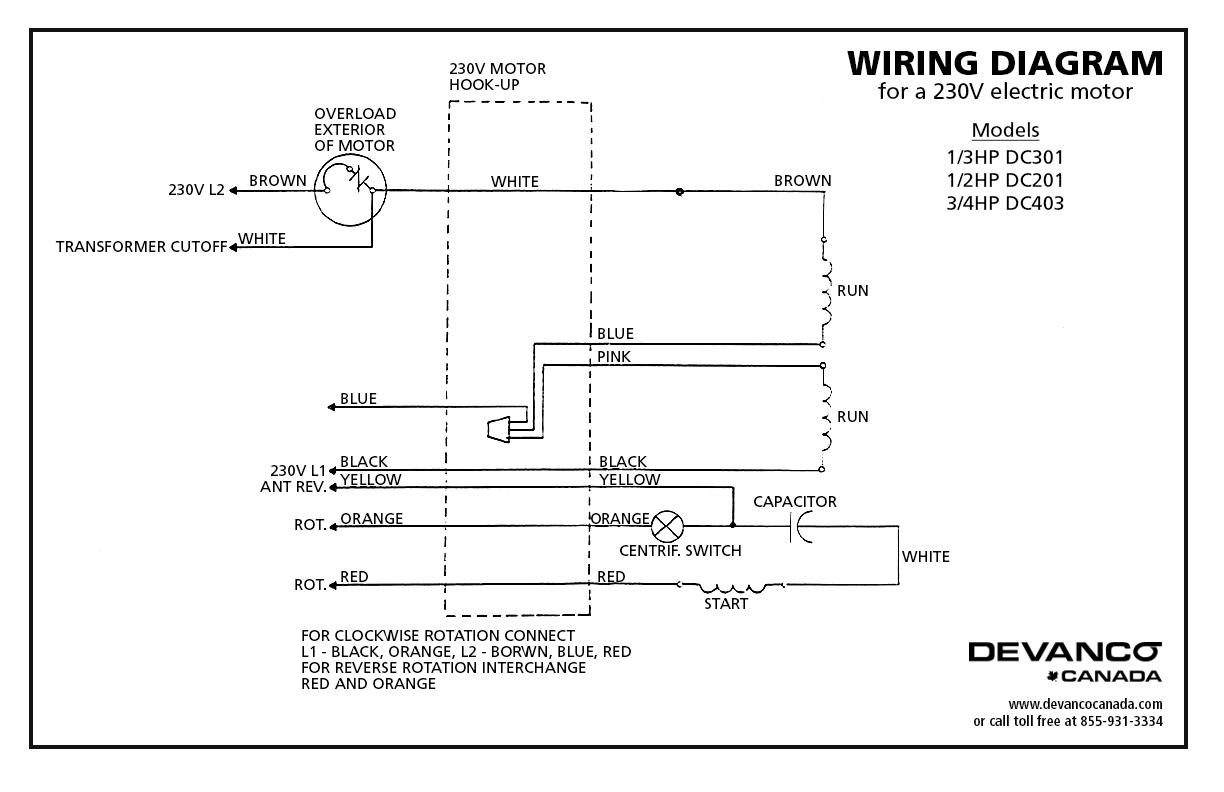
27024 - Doorlec Electric Motor TEFC 34HP 115230V DC403

Emerson Electric Motors Wiring Diagram | Free Wiring Diagram

Trying to decide on a 2 or 3 pole drum switch for my ...
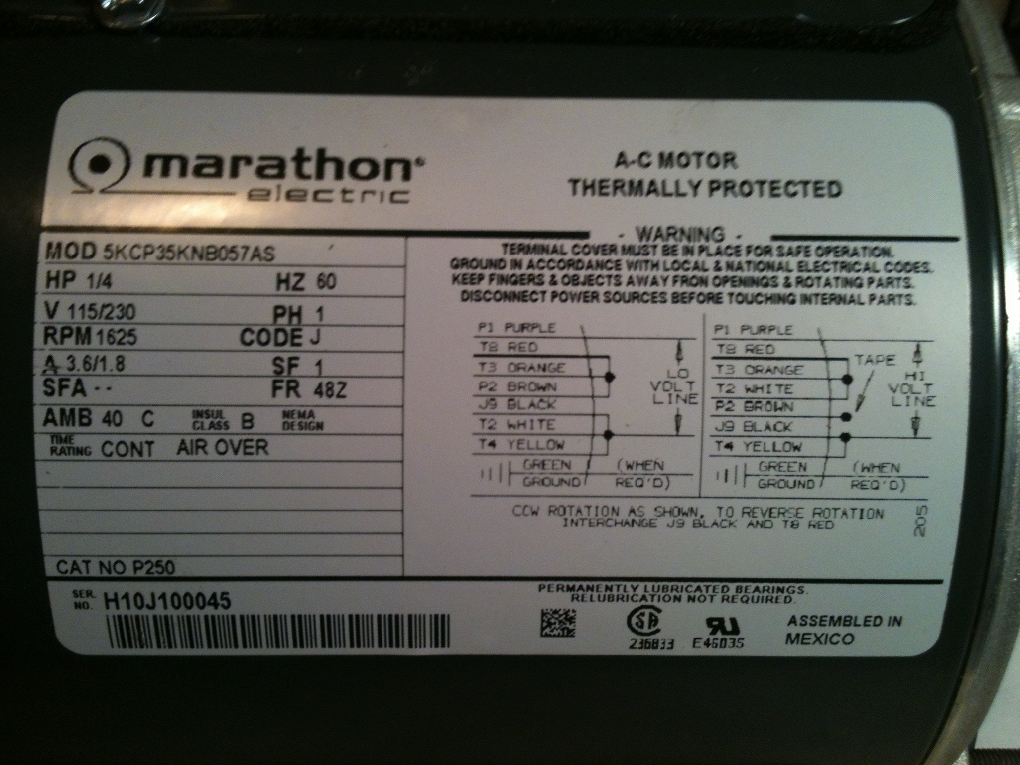
Marathon 3/4 Hp Motor Wiring Diagram

Franklin motor QD 3 wire control box

Leeson Motor Wiring Diagram | Free Wiring Diagram
Franklin Electric submersible motors are designed to operate with a cooling flow of water over the motor. An adequate flow of cooling water over the motor. Testing a blower fan motor winding: referring to the electrical diagram for your equipment, unplug electrical connectors at the fan motor.

0 Response to "3 On Franklin Electric Motor Wiring Diagrams"
Post a Comment