V Switch Wiring Diagram
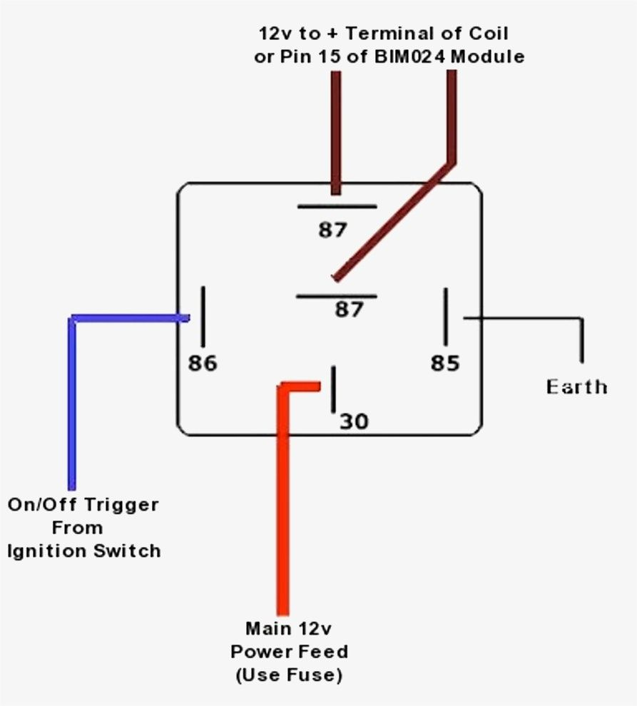
V Switch Wiring Diagram. The diagram explains that the power source is coming in. Wiring diagrams are highly in use in circuit manufacturing or other electronic devices projects.

NOTE: This diagram is a thumbnail.
Instructions: Right click on the diagram/key/fuse box you want to download.
The diagram explains that the power source is coming in. For additional Wiring Diagrams info, see Electrical System (E) in the Technical Bulletins Index. Wiring diagrams show how the wires are connected and where they should located in the actual device, as well as the physical connections between all Most symbols used on a wiring diagram look like abstract versions of the real objects they represent.


0 Response to "V Switch Wiring Diagram"
Post a Comment