V Light Sensor Wiring Diagram
V Light Sensor Wiring Diagram. How to Install PIR Motion Sensor connection & Diagram. As per the circuit diagram, we have made a voltage.
More often than not, you're going to have a ceiling light fixture at the location you are planning on installing a ceiling fan.
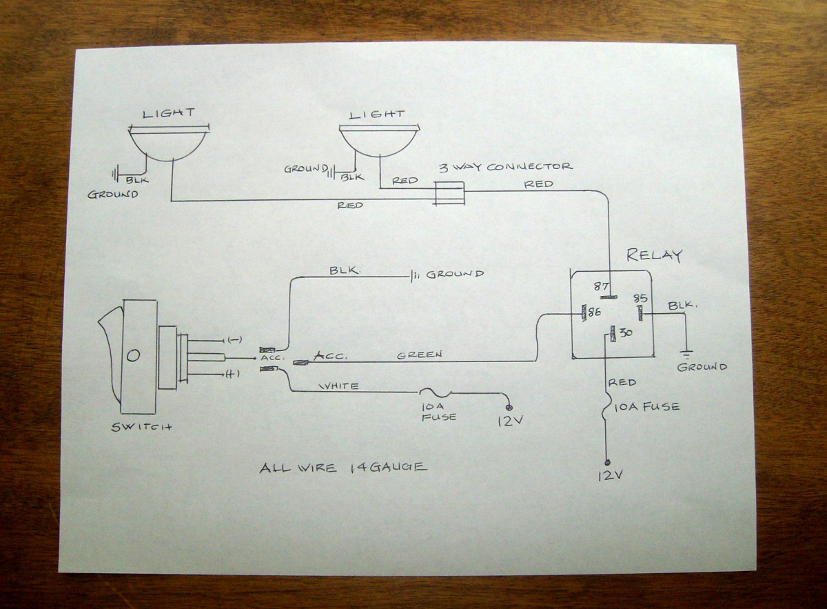
Here is my wiring diagram ( third photo) and instructions Connect red sensor wire to light's black wire.

17 Perfect How To Wire A, Volt Light Switch Solutions ...

Combo Switch (Fan+Light / 110v) to 2 Gang Timer Switch ...

Wiring diagrams electrical circuits

120V Electrical Switch Light Wiring Diagrams | Fuse Box ...

120V Electrical Switch Light Wiring Diagrams | Fuse Box ...

On Off On toggle Switch Wiring Diagram | Free Wiring Diagram

3 Pole 4 Way Rotary Switch Wiring Diagram Three Multiple ...
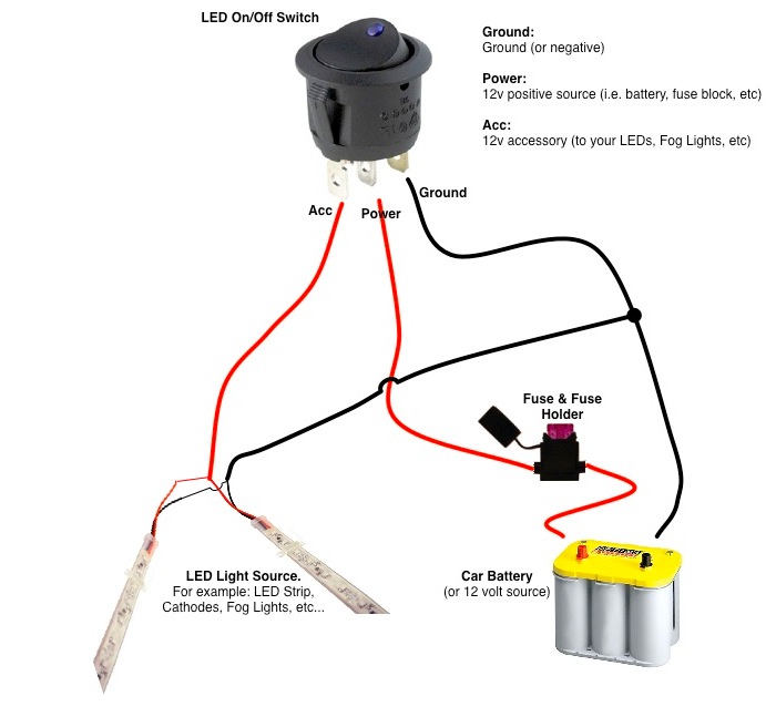
Round Rocker Switch - 12V LED - Prewired in Blue, Red ...

12 Volt Toggle Switch Wiring Diagra | Automotive ...
How can I install an outdoor light sensor? IAT sensor to the wiring of the MAF sensor since it has a built in IAT sensor. anyone know the wire config of the MAF sensor?? wire from the sensor to the ecu, I don't know which are the corresponding wires with the stock MAP wiring. • Ambient Light Detection (ALD): Lights turn on only if natural light in room is low - Smart—Ambient light threshold adjusts to the user's • The performance of the sensor dimmer depends on a temperature differential between the ambient room temperature and that of room occupants. The use of sensors and wired or wireless connectivity in lighting systems enables improved energy efficiency and enhanced occupant comfort.

0 Response to "V Light Sensor Wiring Diagram"
Post a Comment