Yamaha Outboard Gauge Wiring Diagram Picture
Yamaha Outboard Gauge Wiring Diagram Picture. On the other hand, the diagram is a simplified version of this arrangement. boat tach wiring wiring diagram user yamaha outboard tach wiring wiring diagram long. The diagram provides visual representation of an electrical structure.
Wiring diagrams will next improve panel schedules for.
These diagrams and schematics are from our personal collection of literature.
Yamaha Outboard Engine Wiring Diagram - Wiring Diagram Schemas
Yamaha Digital Gauge Trim not working - The Hull Truth ...

Yamaha Outboard Wiring Diagram - Hanenhuusholli
Yamaha Digital Tach Wiring Diagram - Wiring Diagram Schemas
YAMAHA Marine - Digital network Gauge - Round Multi ...

Yamaha 704 Remote Control Wiring Diagram - Wiring Diagram
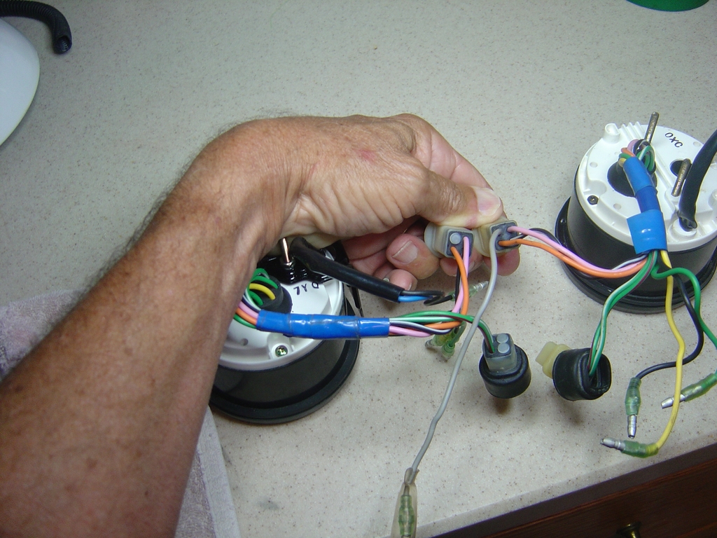
Yamaha Outboard Digital Gauge Repair - Digital Photos and ...
Yamaha 90 Outboard Wiring Diagram - Wiring Diagram Schemas

Yamaha Smart Gauge Wiring Diagram - Wiring Diagram Schemas
The latest DEC Drive-by-Wire controller now has a simple. SaveSave Yamaha outboard engine service manual For Later. The outboard warning system incorporates warning light gauge (a) and warning horn (b).

0 Response to "Yamaha Outboard Gauge Wiring Diagram Picture"
Post a Comment