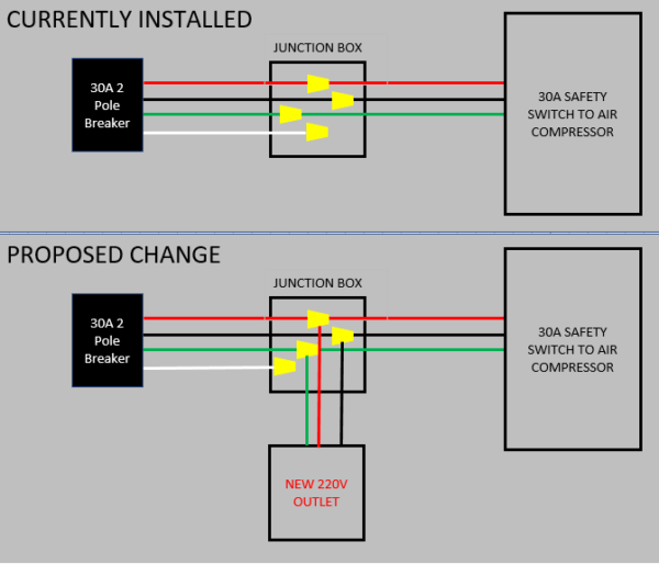
V Outlet Wiring Series Diagram
V Outlet Wiring Series Diagram. Free wiring diagram and tutorial inside! Wiring a GFCI outlet may vary slightly from manufacturer to manufacturer, but for the most part, they follow the same general principles.

In this simple wiring diagram, multiple outlets have been connected in parallel.
Wiring in Series or Daisy-Chained vs.
Design conforms to foreign safety standard (UL/CSA/TUV). Type of wiring diagram Wiring Diagram VS Schematic Diagram How to read a wiring diagram: Symbols you should know Wiring Diagram A wiring diagram can also be useful in auto repair and home building projects. It shows the components of the circuit as simplified shapes, and the power and signal connections between the devices.


0 Response to "V Outlet Wiring Series Diagram"
Post a Comment