Voltpressor Wiring Diagram
Voltpressor Wiring Diagram. Typical Submersible Pump Wiring Diagrams & Connections. Connector numbers enclosed by frame are indicated with the connector symbols at the lower part of the page.
Onboard chargers are equipped with positive and negative leads for each battery.
My wire from the sensor is about.
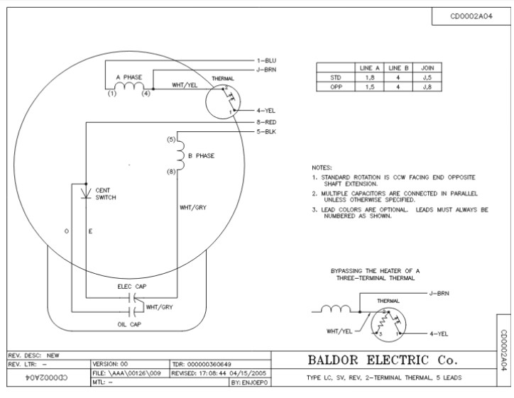
Baldor 5hp Single Phase Motor Wiring Diagram - Wiring Diagram

Thomas Skid Steer Wiring Diagram - Wiring Diagram
120 Volt Copeland Compressor Wiring Diagram
34 12 Volt Hydraulic Pump Wiring Diagram - Wiring Diagram ...

Wiring Diagram PDF: 120 Volt Copeland Compressor Wiring ...

34 12 Volt Hydraulic Pump Wiring Diagram - Wiring Diagram ...

Wiring Diagram PDF: 120 Volt Copeland Compressor Wiring ...
120 Volt Copeland Compressor Wiring Diagram

Wiring Diagram PDF: 120 Volt Copeland Compressor Wiring ...
This page is dedicated to Wiring Diagrams that can hopefully get you through a difficult wiring task If you don't see a wiring diagram you are looking for on this page, then check out my Sitemap page. Following table shows wire colors related to electrical circuits. F ELECTRICAL WIRING DIAGRAM (System Circuits).

0 Response to "Voltpressor Wiring Diagram"
Post a Comment