Volts Electric Motor Wiring Diagrams
Volts Electric Motor Wiring Diagrams. Typical Dual Circuit Alternator Wiring Diagram. A DC motor has two input terminals, one.

First, we will look at how a DC motor works in a linear actuator.
An electric motor is an electrical machine that converts electrical energy into mechanical energy.
Century Ac Motor Wiring Diagram 115 230 Volts | Wiring Diagram

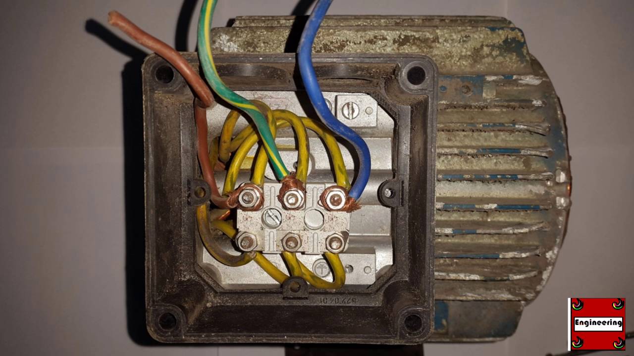
Wiring Baldor motor

Collection Of Wiring Diagram Century Electric Company ...
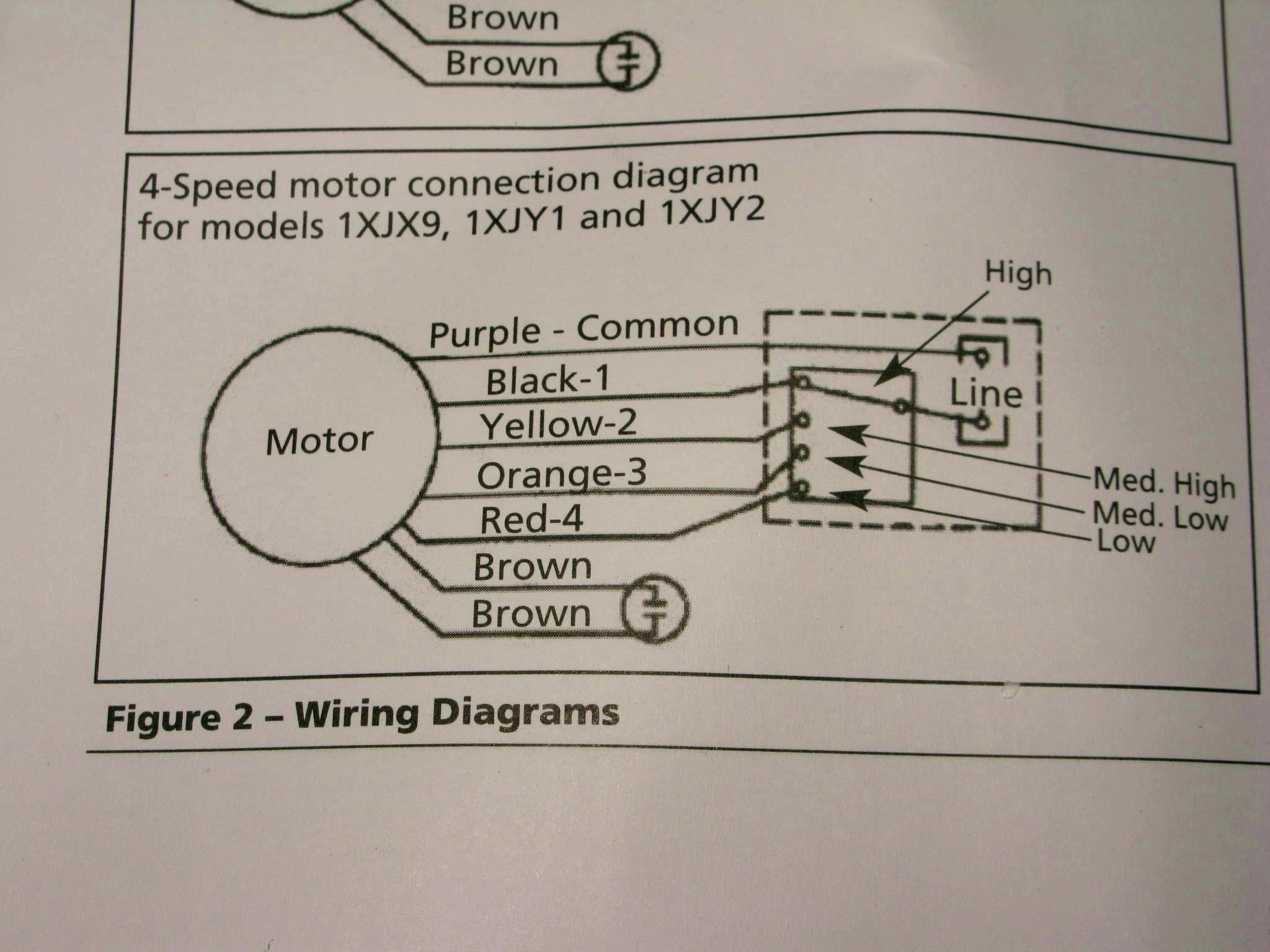
110/220 Volt 6 Pole Induction Motor Wiring Diagram
Mac 24 Volt 400 Watt Brushless Motor Wiring Manual from ...
Wiring Motor for 110v Please Help! - by Blake ...

Electrical Control Circuit Schematic Diagram of Capacitor ...

Wiring Diagram For 220 Volt Air Compressor | wiring ...

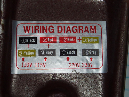
Wiring Diagram For 220 Volt Single Phase Motor, http ...
A wiring diagram is a kind of schematic which uses abstract pictorial symbols showing each of the interconnections of components in the system. These diagrams are current at the time of publication, check the wiring diagram supplied with the motor. Typical Dual Circuit Alternator Wiring Diagram.

0 Response to "Volts Electric Motor Wiring Diagrams"
Post a Comment