V Receptacle Wiring Diagram
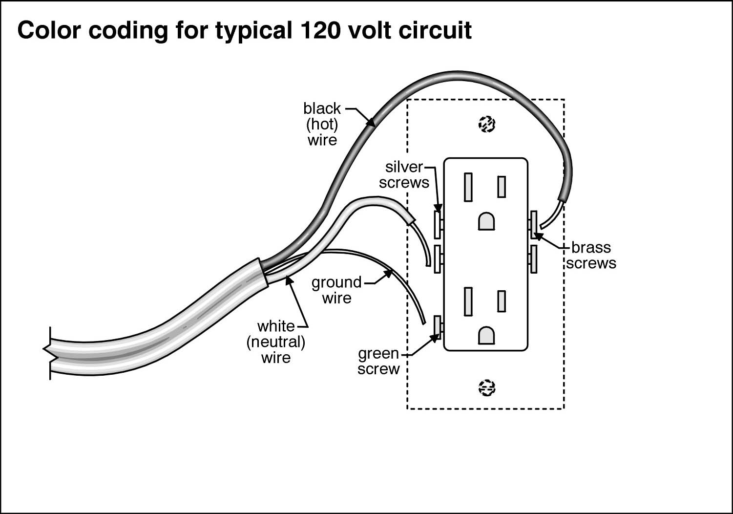
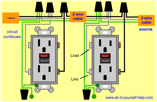
V Receptacle Wiring Diagram. Wiring Diagram For House Outlets - bookingritzcarlton.info. On the other hand, the diagram is a simplified version of the arrangement.

A wiring diagram is a kind of schematic which uses abstract pictorial symbols to exhibit each of the interconnections of components inside a system.
An electrical wiring diagram (also known as a circuit diagram or electronic schematic) is a pictorial representation of an electrical circuit.
C. electrical interlock and DC magnet coil. A wiring diagram is a visual representation of components and wires related to an electrical connection. Wiring diagrams are made up of a pair of things: symbols that represent the.


0 Response to "V Receptacle Wiring Diagram"
Post a Comment