Volt Single Phase Motor Wiring Diagrams
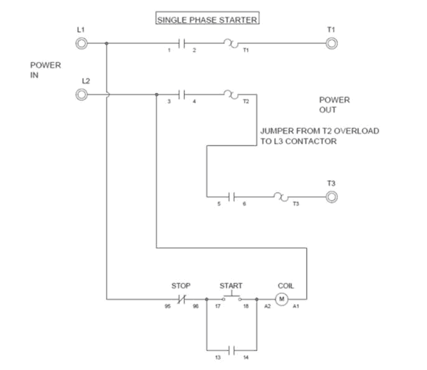
Volt Single Phase Motor Wiring Diagrams. Split-phase motor is a single-phase induction motor having an auxiliary (starting) winding on the stator, offset from the main one, and a squirrel-cage rotor. The above diagram is a complete method of single phase motor wiring with circuit breaker and contactor.
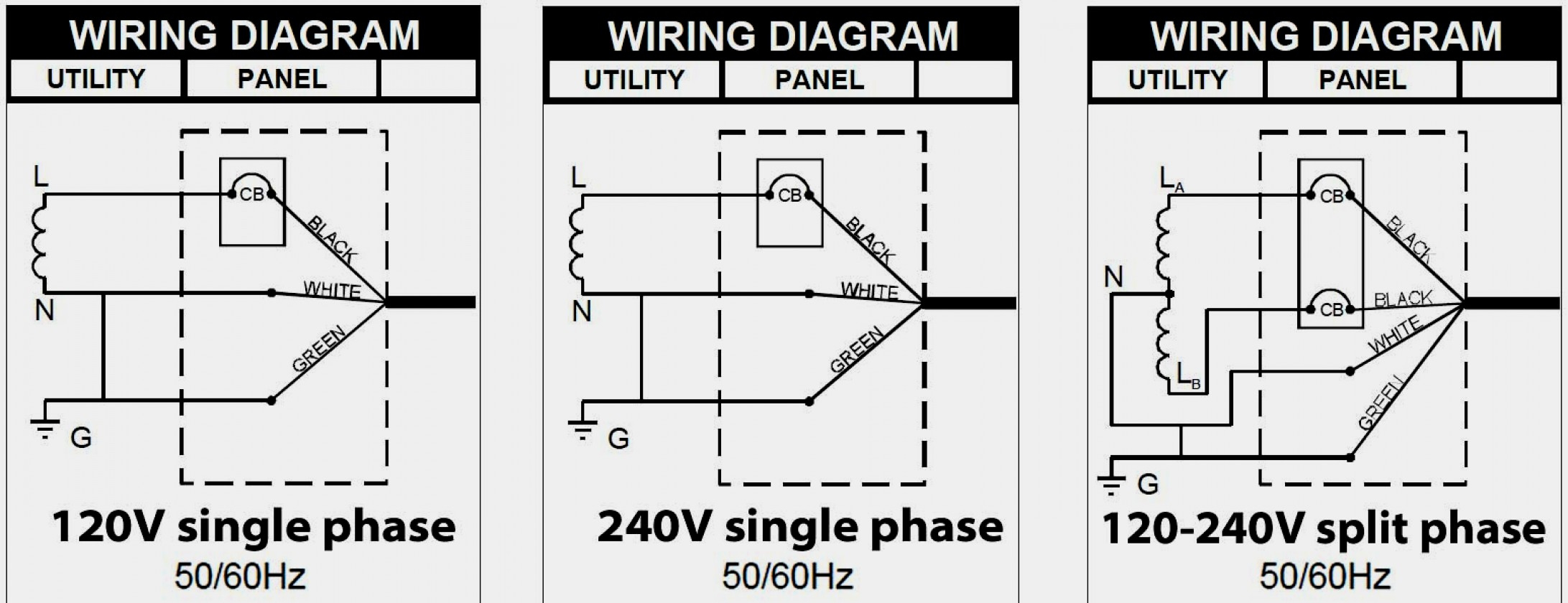
Wiring diagrams or connection diagrams include all of the devices in the system and show their starting and protecting small, single phase, two-. is mounted in the same enclosure to allow.
The post discusses a single phase variable frequency drive circuit or a VFD circuit for controlling AC The above settings will determine the correct volts per Hertz (V/Hz) for the particular motor.

240v Motor Wiring Diagram Single Phase Collection

Hyderabad Institute of Electrical Engineers: wiring ...

[DIAGRAM] 5 Hp Electric Motor Single Phase Wiring Diagram ...

Dual Voltage Single Phase Motor Wiring Diagram Kanvamath ...

240V Motor Wiring Diagram Single Phase - Database - Wiring ...
240 Volt Single Phase Motor Wiring Diagram - Collection ...
[DIAGRAM] Single Phase 240v Transformer Diagram FULL ...

240 Volt Single Phase Motor Wiring Diagram - Collection ...

240v Motor Wiring Diagram Single Phase | Free Wiring Diagram
Because there is a backward-rotating component of flux, there are pulsating torques, so the torque-speed curve is really just a representation of the average torque. If we left a capacitor in the auxiliary winding after. Split-phase motor is a single-phase induction motor having an auxiliary (starting) winding on the stator, offset from the main one, and a squirrel-cage rotor.

0 Response to "Volt Single Phase Motor Wiring Diagrams"
Post a Comment