Trolling Motor Wiring Diagram
Trolling Motor Wiring Diagram. A wiring diagram is a simple visual representation of the physical connections and physical layout of an electrical system or circuit. According to previous, the traces at a Trolling Motor Wiring Diagram represents wires.

However, it doesn't imply connection between the wires.
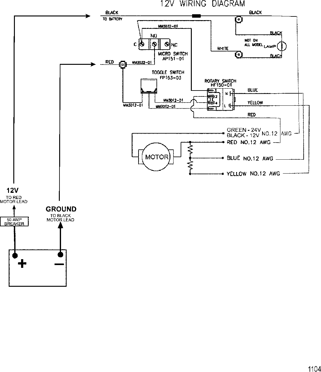
Basic wiring for motor control - Technical data.

3 Wire Trolling Motor Wiring Diagram - Collection - Wiring ...
Johnson Trolling Motor Wiring Diagram

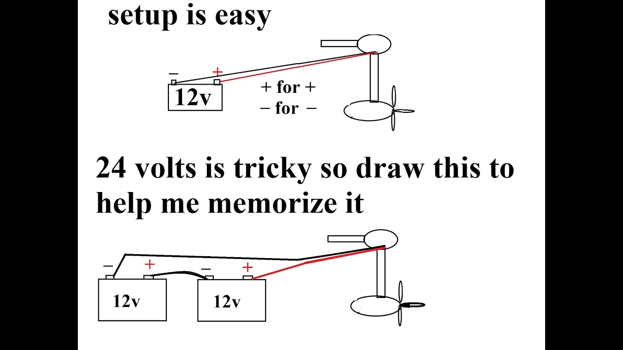
24 Volt Trolling Motor Wiring Diagram | Fuse Box And ...

24 Volt Trolling Motor Wiring Diagram | Fuse Box And ...
How to Wire a Kill Switch for a Kayak Trolling Motor ...
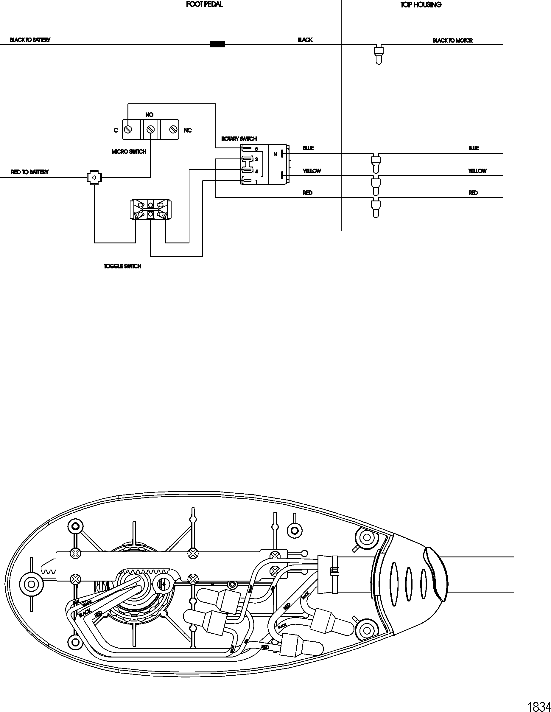
Wiring Diagram Motorguide Trolling Motor
36 Volt Trolling Motor Wiring Diagram | Wiring Diagram

Motorguide Trolling Motor Wiring Diagram: Motorguide ...
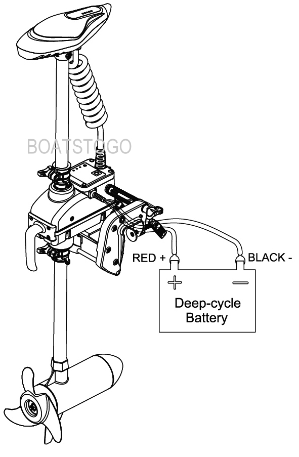
Remote Controlled 55Lbs 12V Electric Trolling Motor.
It shows the components of the circuit as simplified shapes, and the power and signal connections between the devices. You can find your model year in the form below. Double check your motor's voltage for proper connections.

0 Response to "Trolling Motor Wiring Diagram"
Post a Comment