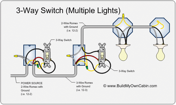
V Light Switch Wiring Diagrams
V Light Switch Wiring Diagrams. For additional Wiring Diagrams info, see Electrical System (E) in the Technical Bulletins Index. One pilot light may be used to indicate operation at both low and high speeds.

HOW T O READ THE WIRING DIAGRAMS Contents of Wiring Diagrams.
Connector numbers enclosed by frame are indicated.
No. as in the wiring harness diagram is used. Wiring Diagram is a technique for describing configuration of electrical equipment installation for example installation of electrical equipment in substation in CB from panels to CB boxes which include aspects of telecontrol & telesignaling. Contributors to this page include Bryan M, Gerk vd Wal, David Del Vecchio, Andy Thompson, Kurt, John Sonnenberg, Darryl Moore, Bruce A.


0 Response to "V Light Switch Wiring Diagrams"
Post a Comment